Florida Mesh FAQ
 August 13, 2026
21 min read
August 13, 2026
21 min read
Frequently asked questions regarding LoRa, and the Florrida Mesh network.
Florida Mesh
LoRa is a low-power, long-range radio technique for transmitting relatively small pieces of data over distances that Wi-Fi or Bluetooth does not reach.
The network requires all users to have compatible radio parameters (frequency, bandwidth, and other channel settings) so that their announcements and routing information will be mutually understood.
Without MQTT or other internet-based messaging service, packets pass through the mesh completely via radio links. If there is a direct connection between nodes, then the packet can be sent directly. If not, other nodes in-between will relay it.
It is similar to passing whispers in a classroom.
You whisper your message to the person sitting behind you – this is your radio link.
This person relays the message to the next one – this is one hop.
Your message passes from person to person until it reaches the addressee.
Each radio link/node acts as both a user and a relay (when configured properly) for messages for others.
Not all radios have the same power or antenna setup and they all have their own obstacles. One thing would be to get two nodes, have one of them transmitting at intervals (within the app settings) and then take your other node and move around to see where you can receive. You could plot that information on a map and get an idea of your real world max radius under different conditions. The world is dynamic, things change quickly. So it can be hard to tell how well things are working without ground truthing it yourself - and your mileage may vary compared to another person with different hardware.
Generally people wouldn’t mind somebody taking an hour or two to experiment with their nodes, just make sure to turn off all unnecessary transmitting when done.
With a single node it is a lot harder. You have to be clever about how to test.
Radio
Radio is a technology that uses radio waves to communicate information. Radio waves are part of the electromagnetic spectrum which is a combination of two tightly linked forces in the Universe: Magnetism and Electricity. Changing magnetic fields (magnetism) create electric fields (electricity) and changing electric fields create magnetic fields.
The radio waves are only one part of the electromagnetic spectrum, which ranges between 3kHz and 300GHz with wavelengths of 100km to 1mm. The entire electromagnetic spectrum encompasses Radio Waves, Microwaves, Infrared, Visible Light, Ultraviolet, X-rays, and Gamma Rays - and they all travel at the speed of light in a vacuum.
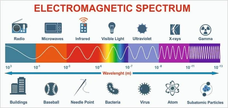
Figure: Electromagnetic spectrum. Adapted from Arucu et al. (2025) [CC BY-NC 4.0] (https://creativecommons.org/licenses/by-nc/4.0/)
The electric and magnetic fields of this spectrum travel in oscillations perpendicular to each other. The perpendicular oscillation of electric and magnetic fields dictates the physical design, orientation, and performance of radio antennas. This geometric relationship manifests practically through polarization, which is defined by the orientation of the electric field affected by the orientation and type of antenna used. In LoRa this is generally a vertically polarized antenna. These oscillations are measured in hertz, which is cycles per second.
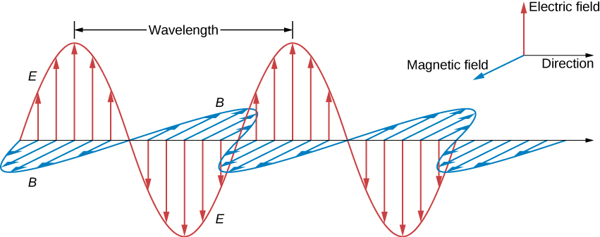
Figure: Representation of a plane electromagnetic wave. Source: University Physics II - Thermodynamics, Electricity, and Magnetism (OpenStax), licensed under CC BY 4.0.
Polarization refers to the specific geometric orientation of the electric field oscillations in a radio wave. Since the electric and magnetic fields are perpendicular, defining the electric field’s direction automatically defines the wave’s polarization.
When someone says that an antenna is vertically polarized this means that the electric portion of the electromagnetic field moves up and down. This polarization is common in terrestrial FM radio, mobile phones, and LoRa. The radiating part of the antenna is vertical.
If the antenna is horizontally polarized then the electrical field moves side-to-side which is common in some older TV broadcasts, and HF Ham Radio. The radiating part of the antenna is physically horizontal.
There are other electric field polarizations such as circular polarization - used by GPS, but is not covered here.
When an antenna of a receiving radio has a mismatch polarization from another transmitting radio, there could be a signal loss of 20dB or more. So, when designing a wireless link between LoRa nodes, matching the polarization of the transmitting and receiving antennas is important for maximizing signal strength. However, engineers do take advantage of polarization differences in order to minimize interference, and use the same frequency for multiple communication channels.
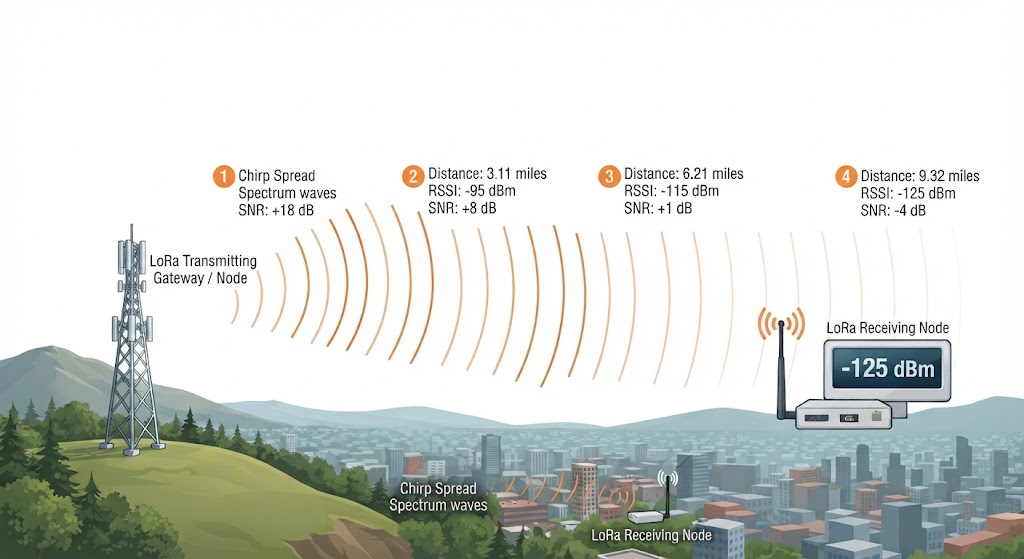
*Figure: Illustrates a LoRa transmission over a distance across a city, demonstrating how signal changes through the measurements of RSSI, and SNR towards a LoRa node 9.32 miles away.
The decibel (dB) is a logarithmic unit used to measure ratios of power or signal. The unit was created in the 1920s at Bell Labs Telephone company to simplify and standardize the measure of loss over distances in telephone wire. In radio and antenna networks it’s used to measure power change between two signals in addition to antenna performance.
SNR (Signal-to-Noise Ratio) indicates how strong your signal is compared to background noise floor. LoRa is designed to accommodate picking up signals below the noise floor (using a technology called Chirp Spread Spectrum) - which makes for better performance in noisy areas, such as urban environments where air conditioners and cars interfere with radio signals.
dBi is the relative ratio of your antenna’s focused power compared to an isotropic radiator. An isotropic radiator is a theoretical radiator that focuses its energy uniformly in all directions. It’s used as a theoretical standard of reference and has a gain of 0dBi and a perfect spherical radiation pattern.
RSSI stands for Received Signal Strength Indicator and it’s a measure of how strong a signal was received from a node and it’s measured in dBm (decibels relative to a milliwatt).
dBm stands for decibels relative to a milliwatt - and is a measurement of the power level coming from an external node. It is an absolute power scale where 0 dBm is equal to 1 milliwatt. Usually in LoRa values range from -60dBm to -120dBm because of the high frequency and low power of the transmissions. As an example: -60 is a stronger signal and -120 is a weaker signal.
dBd stands for decibels relative to a dipole. This is a comparison of the antenna to a dipole antenna instead of a theoretical isotropic radiator. Dipoles have about 2.15dB of gain over an isotropic radiator and this makes them seem like they have a higher gain but since dipoles have a higher gain then an isotropic radiator the baseline is lower. To get dBi from dBd you add 2.15dB. 0dBd = 2.15dBi.
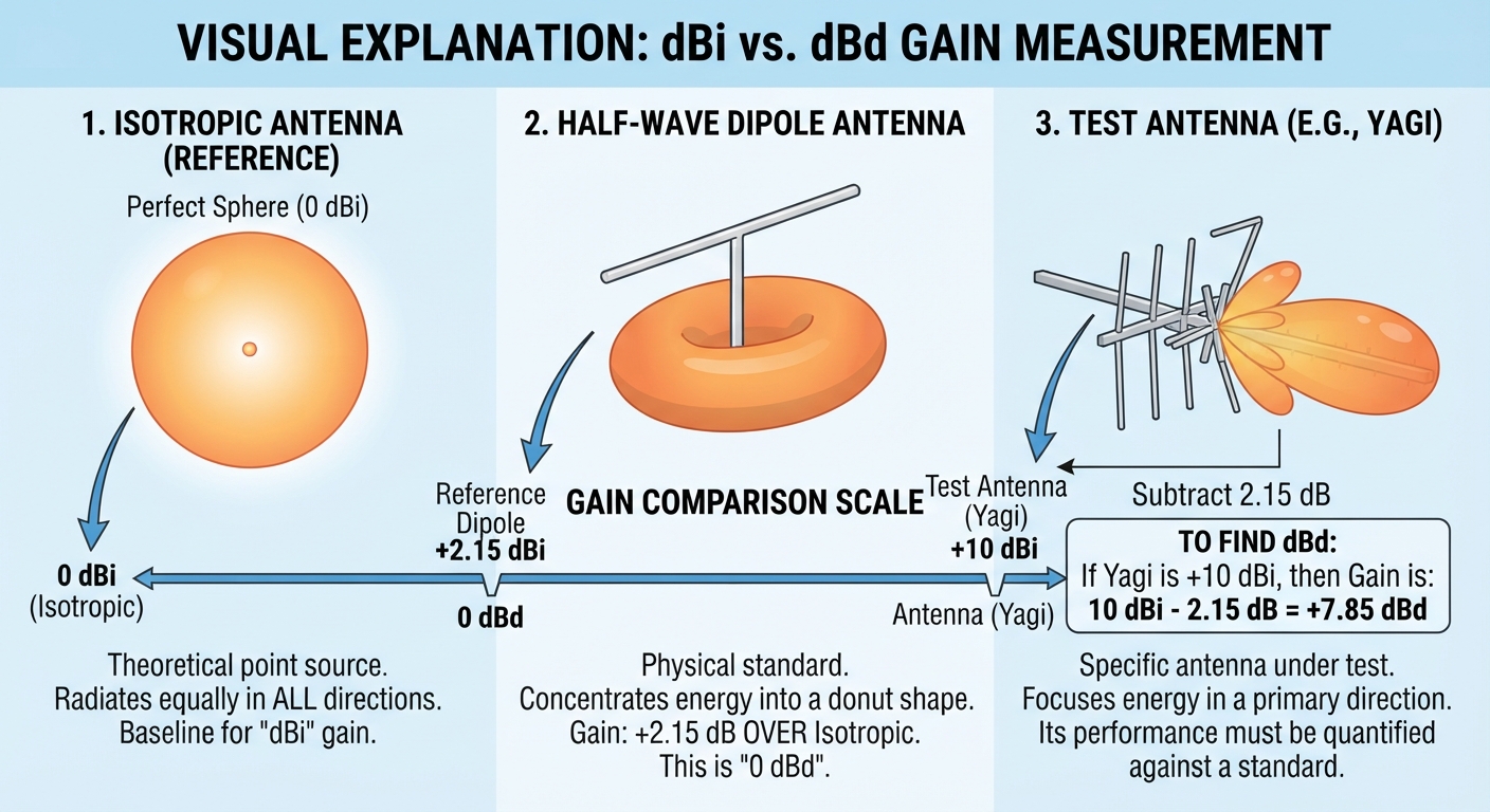
*Figure: Illustrates the difference between dBd and Dbi by comparing Isotropic radiator, dipole, and yagi antenna.
When people refer to the operating frequency of their radio they use terms like hertz, kilohertz, megahertz, and gigahertz. This is a measurement of the oscillations of the electromagnetic waves coming out of the radio in hertz (cycles per second).
Kilohertz (kHz) has the prefix kilo which means thousands - so 1 kilohertz is one thousand hertz, 1,000Hz.
Megaherts (MHz) has the prefix mega which means millions - so 1 megahertz is one million hertz - 1,000,000Hz.
Gigaherts (GHz) has the prefix giga which means trillions - so 1 gigahertz is one trillion hertz - 1,000,000,000Hz.
The radio portion of the electromagnetic spectrum is broken down by the following frequency slots - sometimes called bands. This is a convention used so when radio engineers and hobbyists are talking about radio they know which portion of the spectrum they are referring to:
VLF (Very Low Frequency) - 3-30kHz - This band is commonly used for submarine communication because the long wavelengths can penetrate shallow seawater. It’s also used for Radio navigation beacons.
LF (Low Frequency) - 30-300kHz - This band is used for maritime ship-to-shore communication and transoceanic air traffic control in addition to other navigational beacons.
MF (Medium Frequency) 300kHz-3MHz - AM (Amplitude Modulation) radio broadcasting, coast guard and maritime radio.
HF (High Frequency) 3-30MHz - Shortwave international broadcasting, Amateur (ham) radio operations, and aviation air-to-ground and long-range ocean vessel communications.
VHF (Very High Frequency) 30-300MHz - FM (Frequency Modulation) radio and older television broadcasting, air traffic control, and land mobile systems for public safety.
UHF (Ultra High Frequency) 300MHz-3GHz - Cellphone networks and smartphones, WiFi/Bluetooth/and GPS systems, LoRA, UHF television, and satellite communications.
SHF (Super High Frequency) 3-30GHz - SATCOM satellite communications and satellite TV, point-to-point microwave links, and ground-based radar systems.
EHF (Extremely High Frequency) 30-300GHz - high-capacity cellphone data, automotive collision-avoidance and tracking radar, and radio astronomy.
The frequency is the number of cycles of the electromagnetic wave and the height of the wave.
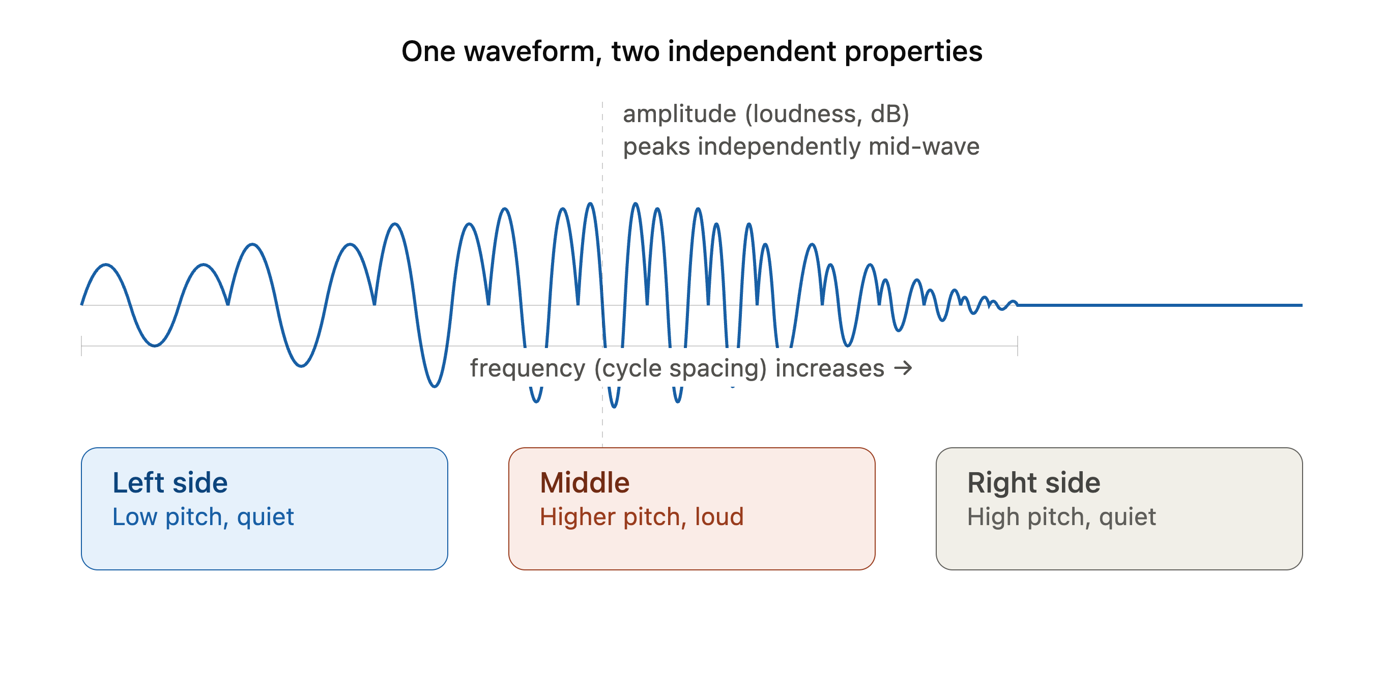
Frequency is which part of the radio section of the electromagnetic spectrum your radio operates on — 902-928 MHz in the US, 863-870 MHz in EU — and this determines where your node’s signal sits in the spectrum, which region’s regulations you’re complying with, and which other Meshtastic nodes you can even talk to (a 915 MHz node can’t hear an 868 MHz one).
Decibels, meanwhile, show up in a few places in the Meshtastic world: transmit power (dBm, how strong your radio’s output is, often capped around 20-30 dBm / 100mW-1W depending on local regulations), and RSSI/SNR (signal strength and quality of a received packet, shown in the app as dB or dBm values like “-110 dBm” for a weak, barely-decodable signal versus “-60 dBm” for a strong nearby one).
These two axes are independent, just like with sound or any radio: your frequency band (915 MHz) stays fixed regardless of how far your signal reaches, while your effective range and reliability depend on transmit power, antenna gain, terrain, and LoRa’s spreading factor — so two nodes on the exact same 915 MHz frequency can have wildly different signal strength (dB) depending on distance, obstacles, and hardware, while a node using more power or a better antenna doesn’t change its frequency at all, just how far and how clearly its signal carries.
Some people complain that 1 watt of power isn’t enough power. Most of these people likely come from traditional radio systems like CB and FRS where more power is equated with longer range. This is a misconception brought on by mass marketing of unlicensed radios, as you’ll notice the difference between flat terrain vs an urban area or forest when operating these radios.
It’s not so much the power that is a limiting factor in radio communication but rather a combination of things: amount of power, operating frequency of the radio, antenna feedline, antenna, and antenna height.
Operating Frequency
The LoRa band operates at the Ultra High Frequency (UHF) band of 902-928MHz which has a wavelength of approx. 1ft. Because of this high frequency and small wavelength it is not affected by the Ionosphere as much as other bands - such as CB. This small wavelength prevents the signal from bouncing off the Ionosphere and keeps the radiation closer to earth - at line of sight. The smaller wavelength is also affected by more things - things around 1ft.
Feedline, connectors, and adaptors
As a general rule of thumb you want to keep your feedline between radio and antenna as short as possible. This is because the type and length of feedline used can affect the signal coming in and out of the antenna drastically. Most individuals install their node within inches of the antenna to reduce feedline loss and this does sometimes come with its own challenges - power, heat dissipation, and weatherproofing.
Most feedline, connectors, and adaptors are 50ohms which impedance matches what most radios use. Read your radio’s manual if you’re not sure about what impedance the line needs to be at. You can create an impedance matching network if your radio doesn’t match the feedline, but the losses through the network maybe too great for what you’re doing. You’ll likely have to calculate the theoretical loss and then use measuring equipment to verify real world scenarios.
Whatever connectors and adaptors you use ensure that they are spec to: the operating frequency; antenna and radio impedance; and power loss across the connectors/adaptors. All connectors and adaptors have loss and you’ll want to reduce the amount of loss between your radio and the antenna.
If you decide that you must have a longer piece of feedline due to infrastructure constraints then you’ll likely need to purchase hardline or a flexible-type line such as LMR-400. This type of cable is an extremely expensive low loss cable. You’ll still likely want to measure loss across the cable but it’s a far superior cable than something like RG-8 - which is fine for HF radio, but very lossy for VHF or higher bands.
Antenna
There are many types of antenna that you can use for LoRa, more than can be covered in a small FAQ, but there are some considerations you should take into account before purchasing or assembling your own antenna. Frequency response, required feedline impedance, and design of antenna are just some of the many factors that go into deciding what antenna to get.
There are many kinds of antenna out there: dipoles, monopoles, and yagi are some of the many kinds.
Dipole
Dipoles are antenna that have two sides. The di- in dipole means two, so a dipole has two poles, two halves both 180 degrees out of phase of each other. The center of the two sides are fed by your feedline. This is the simplest design and easiest antenna to make.
These are omni directional, they will radiate in all directions (depending on frequency and surrounding environment)
Monopole
You usually see these on handheld LoRa radios. They are end-fed and have only one element; an effective monopole requires a ground plane or radial system to prevent mismatched impedance. Oftentimes with handhelds there’s not much you can do about a mismatched impedance, but at home you can construct a ground plane if your antenna lacks one. These antennas are omnidirectional and will radiate uniformly in all directions when paired with a proper ground plane. The ground plane also helps optimize the signal’s takeoff angle.
Yagi
Yagi antennas are constructed of a dipole and any number of other elements behind and in front of the dipole. The dipole to which the feedline connects to is called the radiating element. The elements in front are called directors and the elements behind the dipole are called the reflectors. The dipole is directional and can reduce interference by pointing the antenna at the target station. The elements behind the radiating element prevents radiation from behind the antenna from being picked up and elements in front narrow the beam of radiation towards the station you want to communicate with.
Frequency Response
A lot of people think that the longer the antenna the better reception you’ll get. This is a misconception and a mistake that could cost you your radio. The antenna must match as closely as possible to the operating frequency of your radio otherwise it could damage the radio.
There are a number of factors that go into a good antenna:
Input Impedance
Every antenna has an impedance — think of it as how much “resistance” it presents to the signal trying to flow into it from your radio or transmission line. Most Meshtastic/Meshcore radios use U.FL or SMA connectors which are designed around 50 ohms, and antennas are designed to match that as closely as possible at their intended operating frequency. When impedance matches well, power flows into the antenna and radiates efficiently instead of bouncing back toward the source- along the outer shield of the coax.
Impedance isn’t fixed across frequencies — it shifts as you move away from the design frequency. Right at the antenna’s “sweet spot,” the impedance is closest to ideal. Move off that frequency and the impedance drifts, which is why antennas work best over a certain range and get progressively less effective outside it.
When selecting an antenna try to make sure the impedance of the antenna matches what your radio is expecting or you’ll get mismatches.
Return Loss / VSWR
These two numbers are just different ways of describing the same thing: how much of the signal sent toward the antenna actually gets radiated versus how much bounces back down the cable toward the radio. Return loss is measured in decibels (higher numbers are better — more signal going out, less coming back), while VSWR is a ratio (lower numbers are better, with 1:1 being a perfect match).
In practical terms, a poor match wastes transmitter power, can cause heat buildup in cables or connectors, and in bad cases can even damage a transmitter. A “good” antenna setup typically aims for a VSWR under 2:1 across the band you care about, though many well-tuned antennas do much better than that right at their center frequency.
Gain and Radiation Pattern
Gain - measured in dBi or dBd - describes how effectively an antenna focuses its energy in useful directions rather than spraying it equally in all directions - like a flashlight reflector concentrating light into a beam instead of a bare bulb glowing uniformly. Higher gain means stronger signal in the favored direction(s), but that always comes at the expense of weaker signal elsewhere, since an antenna can’t create energy, only redirect it.
The radiation pattern is the shape of that “beam” — it might be a wide donut around a vertical antenna (equal in all horizontal directions, weak straight up/down), a tight forward-facing lobe for a directional antenna, or something more complex. Choosing an antenna means matching that pattern to your actual use case: broad coverage for a base station, a tight beam for a long-distance point-to-point link, and so on.
Radiation Efficiency
Efficiency is simply the fraction of power fed into the antenna that actually turns into radiated radio waves versus the fraction that gets wasted as heat in the antenna’s materials and connections. A highly efficient antenna radiates nearly everything you feed it; a poor one might waste a significant chunk as warmth in resistive losses, especially in physically small or compromised designs.
This matters most for antennas that are electrically small relative to the wavelength they’re working with (a classic example being compact antennas for low-frequency bands), since squeezing a design into a small space often forces trade-offs that increase loss. A physically larger, well-designed antenna at the right frequency will generally run more efficiently than a shrunken or compromised one.
Bandwidth
Bandwidth is the range of frequencies over which an antenna performs acceptably well — good impedance match, reasonable efficiency, and a stable pattern — rather than just working at one exact frequency. Every antenna has a “sweet spot” frequency it’s designed for, and bandwidth tells you how far you can stray from that spot before performance degrades too much to be useful.
Some antenna designs are inherently broadband, covering wide swaths of spectrum well, while others are narrowband and only perform properly over a small slice of frequencies. The right choice depends on your application: a narrowband antenna is fine if you only ever operate on one frequency, but if you need to cover multiple bands or a wide range, you’ll want a design specifically built for broader bandwidth, often at some cost to gain or physical simplicity.
Height
Since LoRa is at a frequency of 915MHz it is least likely to be affected by the Ionospheric skip like CB, so all communications are at ground level - line of sight. This means to communicate you’ll need to get it away from things that will interfere with it. 915MHz has a wavelength of about 1ft which means anything around 1ft will interfere with it. So, get the antenna high above the trees, and buildings. The higher the better so that it can reach across the horizon towards the radios you want to contact.
Power can only do so much at this frequency and height and distance from obstacles is your friend. Look at the cellphone towers in your area. Cellphones operate at approximately 1 to 2 watts of power, but all of the towers are either on rooftops or high up in towers above the treeline. This is because the radios in the phone are at such a high frequency that they are affected by the terrestrial environment of trees, buildings, cars, and more.
Radio waves can reach their destination through ground wave, sky wave, or space (line-of-sight) propagation, and their
range is often extended by physical mechanisms like tropospheric ducting, reflection off water, and scattering from
metallic buildings.
Skip is the condition where the ground wave is too weak to reach the receiver, and the ionospheric sky wave has refracted back to Earth beyond the receiver’s location.
Propagation explains the path of how a signal goes from a transmitting station to the receiving station.
Ducting is a particular type of radio wave propagation where a layer of the atmosphere (typically the troposphere) traps and guides radio signals, allowing them to follow the curvature of the Earth and travel hundreds of miles beyond normal line-of-sight range.
Ground Wave
A groundwave is a radio wave that travels along the surface of the Earth, hugging the curvature of the surface. The surface of the Earth attenuates the signal and prevents the signal from crossing large distances without assistance from a relay station.
There are several factors that affect how radio waves are effected by groundwave propagation:
Operating Frequency
Lower frequencies like those in the VLF, LF, and MF bands are positively affected by groundwave propagation which allows them to travel long distances. Because of their long wavelength, they are least affected by terrestrial factors like buildings. This allows the waves to travel around the conductive surface of the earth by maintain a continuously curved path.
Higher frequencies (corresponding to shorter wavelengths like HF, VHF, and UHF, including technologies like LoRa) experience severe attenuation and scattering when encountering terrestrial objects. Because they behave more like light, they cannot efficiently bend around large obstacles or the Earth’s curvature; instead, they are heavily absorbed, reflected, or only partially penetrate structures depending on the material composition
Large Bodies of water
Lower frequency radio waves can be affected positively by large bodies of water due to its high electrical conductivity, which provides a means of travel along its surface; however, LoRa is affected differently. Because large bodies of water do not contain any obstacles (trees, buildings, cars) a 900MHz radio wave coming off a LoRa node can travel a longer distance.
Polarization Function
For low-frequency radio waves like AM broadcasts, vertical polarization is an absolute requirement because the electric field vector must stand perpendicular to the ground. If a low-frequency wave were horizontally polarized, the conductive Earth would act like a short circuit, absorbing and destroying the wave almost immediately. By keeping the electric field vertical, the wave can successfully bend and follow the curvature of the Earth. In contrast, LoRa operates in the UHF band where groundwaves do not exist. When a LoRa node uses a vertical antenna (like a rubber-duck whip), it isn’t trying to prevent a short circuit against the dirt; rather, it is simply ensuring that the radio energy spreads out evenly in a 360-degree horizontal circle so that sensors and gateways can communicate without needing precise alignment.
Ground Infrastructure
Low-frequency broadcasting stations require massive physical ground infrastructure, featuring hundreds of buried copper wires radiating outward like spider webs from the base of a towering antenna. This extensive ground screen is necessary to minimize ground resistance in the antenna’s immediate vicinity, giving high-power low-frequency signals an efficient electrical counterpoise to couple with the earth. On the other hand, compact LoRa nodes completely bypass this heavy infrastructure. Because they operate at much higher frequencies and run on battery power, they use a tiny printed circuit board (PCB) ground layer or a simple whip counterpoise to achieve electrical balance internally, requiring zero interaction with the soil beneath them.
Sky Wave
Unlike HF radio waves that rely on sky wave propagation, where signals are refracted by the ionosphere to travel long distances, LoRa operates at sub-GHz or UHF frequencies (e.g., 915 MHz) that typically pass straight through the ionosphere into space without bouncing back to Earth; consequently, LoRa nodes generally utilize line-of-sight, diffraction, or occasional tropospheric bounce (ducting) for extended range, rather than the multi-hop ionospheric reflection that defines HF sky wave propagation, meaning sky wave propagation has negligible impact on standard LoRa reception.
Space (line-of-sight)
Line-of-sight propagation occurs when radio waves travel in a direct, unobstructed straight line between a transmitter and receiver, constrained by physical obstacles and the curvature of the Earth. As the dominant transmission mode for VHF, UHF, and LoRa frequencies, it lacks the ionospheric reflection or ground-hugging characteristics of lower-frequency HF waves. Consequently, maximizing its range relies on increasing antenna height to extend the visible radio horizon rather than depending on atmospheric bouncing or diffraction.
Ducting, Water and other materials
LoRa radio signals are profoundly influenced by environmental barriers, moisture levels, and atmospheric or physical channels, which dictate whether a transmission is attenuated, blocked, or unexpectedly extended.
Physical structures like buildings—especially those containing concrete, brick, and steel—introduce heavy attenuation and multipath interference, causing typical urban ranges to shrink to a couple of kilometers as walls absorb and reflect the sub-GHz energy. Water molecules are potent absorbers of radio frequency waves; consequently, heavy rain, high ambient humidity, or moisture trapped inside building materials significantly degrade signal strength and increase packet loss.
Meanwhile, “ducting” refers to unique propagation behaviors. Atmospheric or tropospheric ducts—frequently forming over large water bodies due to temperature and vapor gradients—trap and refract radio waves along the curvature of the Earth, sometimes extending LoRa transmission ranges well beyond normal limits. Conversely, physical metal ducts, such as industrial HVAC systems, can act as unintended waveguides or shielding barriers, either channeling signals down restricted corridors or creating severe local dead zones.